COOL was used during a student project to implement a fuzzy controller on a heterogeneous target architecture. The task of the fuzzy controller is to control the traffic lights at a certain crossing of a main street and a side street. This crossing contains three different lanes as depicted in the following figure.
The idea is to control the traffic lights depending on the number and the waiting time of cars in each lane. The goal of the fuzzy controller is to minimize the average latency of the cars. The principle functionality of the fuzzy controller is depicted in the next figure.
For each lane the fuzzy controller uses the same modules to compute an urgency metric to get the green-signal. To reuse the same modules for each lane allows to apply hardware sharing to minimize the total costs during the design process. The modules for each lane have the following inputs: the waiting time, the number of cars and a boolean value representing whether a pedestrian is waiting or not. Like most fuzzy controllers, these inputs (representing linguistic variables) are fuzzified in a first step computing linguistic terms for the inputs. Then, the inference applies some rules stored in a rule base to the linguistic terms. After this, the resulting values are defuzzified into discrete output values, here the urgency metric presented above. Finally, the lane with the highest value of this urgency metric gets the green-signal. First, the fuzzy controller was specified with COOL. The way of specifying systems in COOL is very well suited for this example, because the modules of the fuzzy controller can be specified by different system components which are instantiated for each lane afterwards. The resulting system specification consisting of 31 instances of 7 system components is depicted.
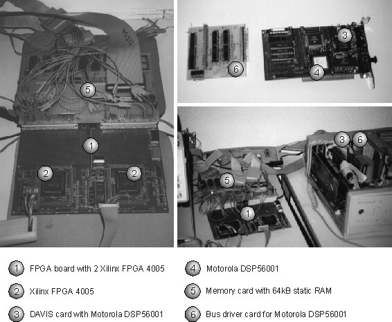
In total, the behavioral VHDL specifications consist of 900 loc (lines of code). The goal was to implement this fuzzy controller specification on a target architecture as depicted in the following figure. containing
To validate the correctness of the resulting hardware/software system, the students developed a prototyping environment, using
All these cards and boards were connected using an 8-bit data bus and a 16-bit address bus as depicted in the next figure.
The prototyping board looks as follows:
The main disadvantage of this prototyping board was the limited amount of hardware resources with 2x 196 CLBs and 2x 61 pins. Most of the specified components of the fuzzy controller could not be implemented on the FPGAs due to the lack of CLBs. To implement the fuzzy controller on the prototyping environment, the hardware/software partitioning was driven by designer defined mapping constraints resulting in the following hardware/software partitioning.
The computed partitioning consisted of 15 nodes implemented in hardware and 16 nodes implemented in software. Afterwards, all co-synthesis steps (generation and optimization of the STG, memory allocation, specification refinement, controller and netlist generation) were executed resulting in the netlist depicted in the following figure.
Then, the refined C specification for the Motorola DSP (961 loc) was compiled into assembler code (5305 loc) and into a binary file afterwards. The hardware parts implemented on the ASICs were partitioned into two separated VHDL descriptions (one for each FPGA) manually, because otherwise pin constraints were violated. The system controller and the I/O controller were implemented on the first FPGA, the bus arbiter, the hardware data paths and their controllers on the second FPGA. Then, both VHDL descriptions (1266 loc) were synthesized by Synopsys and afterwards the Xilinx tools generated the specific configuration files for the FPGAs. The result was a utilization of 80% for the first and 85% for the second FPGA. After this, the binary file for the DSP was down-loaded to the Davis-card using the PC and both FPGAs were configured by down-loading their configuration files from a workstation. At this time, the system could be started using a special simulation environment implemented on the PC generating the values for the inputs and visualizing the results of the fuzzy controller. The correct behavior of the hardware/software implementation was checked with the help of a logic analyzer which is very helpful to find errors in the design or on the prototyping board. Most importantly, this application study proves that the design flow of COOL results in hardware/software systems that are operational and that COOL represents a complete hardware/software codesign tool. Different alternatives of hardware/software partitions were implemented for the fuzzy controller and in all cases the time to execute the complete design flow from system specification to an implementation on the prototyping environment took not more than 60 minutes. The time-consuming factor was hardware synthesis consuming about 90% of the design time. Finally, the functionality of a netlist generated by COOL will be described with the help of the partitioned fuzzy controller (see figure). The simulated netlist itself is depicted in the following figure. In the following figure the results of executing co-simulation with COOL using Vantage Optium are depicted. The depicted part of the simulation illustrates the initialization phase and the computation of the first result computed for a set of input values. The main events are enumerated and will be described.