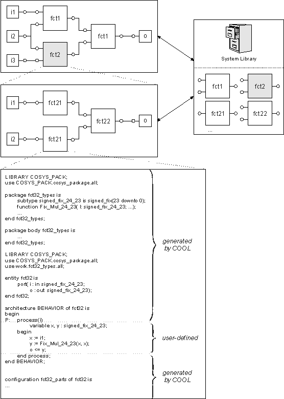
In COOL, systems are specified in a hierarchical manner using an integrated graphical user interface. The specification is based on the language VHDL. System components are specified using either behavioral or structural VHDL. The behavioral descriptions are specified textually. In contrast, the structural specifications are defined by wiring instances of pre-defined system components using the graphical user interface. A system library has been integrated to store specified systems in library classes allowing the designer to define the system either top-down or bottom-up. In the following figure, the specification technique is illustrated.

The specified system consists of two instances of component fct1, described behaviorally, and one instance of the structural component fct2. Component fct2 itself, consists of three instances of components fct21 and fct22. All these components are stored in the system library. To specify a system behaviorally, a designer first has to define the incoming and outgoing signals using COOL. Then, COOL generates a template including the required libraries and types for specifying the component. After this, the designer is able to define the behavior of the component by implementing the empty process statement. In the depicted case, fct32 returns the output o representing the square value of the input signal i.
Semantics of a system specification is data flow oriented. The components communicate via signals, defined graphically by wires. These signals represent abstract communication channels. To be able to estimate the communication effort exactly, a component reads data using the incoming signals at the beginning of the process. Then, the component computes some results for the inputs. Finally, the results are written using the output signals. However, during computation no additional data can be read in, because otherwise the communication effort cannot be estimated exactly.
At the lowest level of hierarchy, the system consists of wired behavioral VHDL specifications. In later design steps, each of these behavioral components is mapped to a processing unit of the target architecture. Therefore, the behavioral description represents the smallest granularity for partitioning which cannot be partitioned onto different processing units.
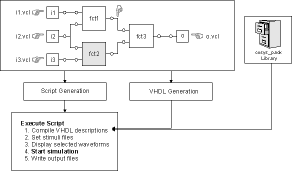
A great advantage of COOL is the integration of the commercial VHDL simulator Vantage Optium as illustrated in the following figure.

Using the graphical user interface, the designer defines the stimuli files for the input signals and selects the signals for which waveforms should be depicted during simulation. Systems described behaviorally can be simulated directly. For structural systems a simulatable VHDL description is generated. In addition, a script is generated which is executed afterwards. This script steers the simulator, by compiling all necessary files including the VHDL package (cosys_pack.vhdl), loading the stimuli files for simulation, preparing and starting the simulation tools, etc. After the simulation has finished, the user can check the functional correctness of the specified system. This interface between COOL and Vantage Optium has been proven to be very helpful in practice, because it automates time-consuming manual work. The integration of Vantage Optium is not only used for simulating the system specification, but also for simulating the results of the design process. This allows the comparison between the simulation results of the specification and the results of the refined system specification after hardware/software partitioning.
Another advantage of COOLhardware/software is that all additional design information, including the definition of the target architecture and design constraints can be specified. Therefore, COOLhardware/software represents a unified design environment for implementing hardware/software systems starting from a homogeneous, implementation-independent system-level specification. In particular, the specification of design constraints is very important, because the experience of the designer should be used during the design process. In COOL, a variety of different constraints are supported, including
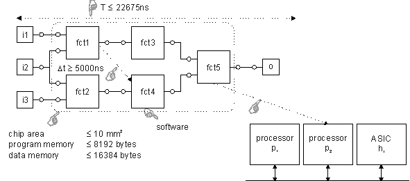
In the following figure, some of these user-defined constraints are depicted.

A mapping constraint has been defined for fct4. It should be implemented in software in general, either on processor p1 or p2. fct5 has to be implemented on processor p2 representing a binding constraint. Two different timing constraints have been specified. First, the complete system execution time T has to be smaller then 22675 ns (real-time condition for audio systems using a sample frequency of 44.1 kHz). Second, a relative timing constraint determines that fct4 may not start earlier than 5000 ns after fct1 has finished. Finally, resource constraints (chip area <= 10mm^2, ...) have been defined for all components.