
An overview of the design flow in COOL will be given with the help of some snapshots showing some steps during the design process of hardware/software systems with COOL. To get more information about COOL, the interested reader is referred to the more detailed descriptions on the different HTML pages.
COOL includes a graphical user environment, depicted in the following figure.
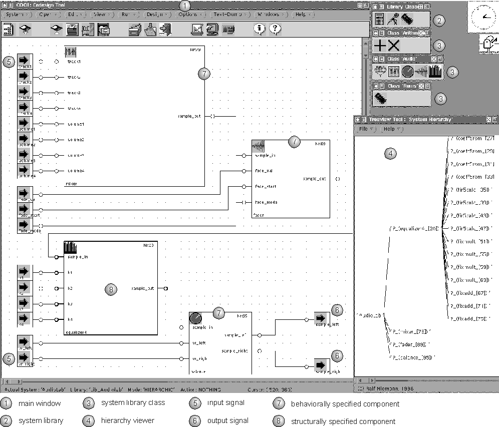
The main window (1) is used for specifying a system graphically by instantiating pre-defined components. These pre-defined components are stored in classes (3) of the system library (2). Using the drag-and-drop technique, systems can be specified. Each specified system can then also be stored in the system library. Therefore, the specification methodology can be either top-down or bottom-up and the resulting systems may be hierarchical. For this reason, the designer can go down the hierarchy from the top to the bottom level. In addition, a hierarchy viewer (4) has been implemented to give the designer an overview of the structure of the system. In the example given, an audio application is depicted. It consists of several input ports (5), two output ports (6) and four instances of pre-defined system components. Three of these components represent behavioral VHDL} descriptions (7), one has been structurally specified (8) illustrated by the bold outline.
To validate the correct functionality of a system, the commercial VHDL} simulator Vantage Optium has been integrated in COOL. In the following figure, an audio fader has been specified by a behavioral VHDL description (1).
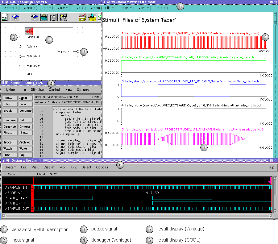
The user has defined the stimuli files for the input signals (2) and some result files for the output signals (3). After the simulation has been prepared, the Vantage Optium} simulator (4) is started. After the simulation has finished, the result display (5) of Vantage Optium} displays the resulting waveforms for all signals. One problem is that some values are fixed-point numbers, being a subtype of bit vectors in COOL. Therefore, it is difficult to check the results with the results display of Vantage Optium}, because data can only be displayed as binary, octal, decimal or hexadecimal numbers. The result viewer (6) integrated in COOL allows a comfortable visualization possibility, because fixed-point numbers are supported and displayed as x-y-plots. In this example, sample_in} represents an alternating signal. fade_value} is constant 0.05 defining that incoming samples are faded in or out with 5% reduction. First, the incoming samples are faded in, and afterwards the samples are faded out. Therefore, the waveform of the output signal sample_out} (3) is correct.
A great advantage of COOL is that the graphical user environment provides a unified design environment. In addition to the specification of the system, the design constraints are also specified graphically. The possibility of specifying a variety of design constraints is very important to exploit the experience of the designer. In the next figure, some examples of design constraints supported in COOL are given.
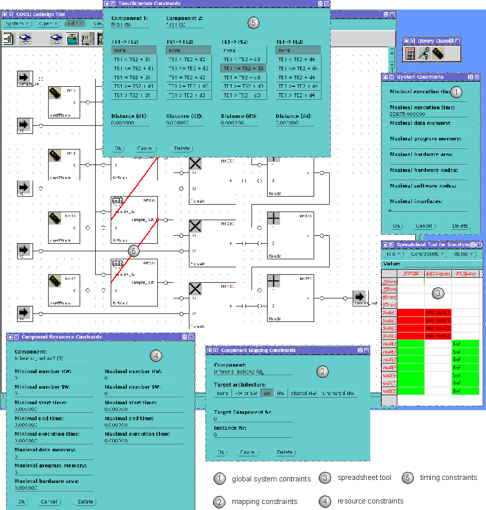
First, the designer is able to define global timing and resource constraints (1) related to the overall design costs (e.g. execution time, hardware area, memory usage). In addition, he can determine mapping and resource constraints. These constraints can be defined for single instances of components, for all instances of a certain component and for each group of instances. The definition of these mapping/resource constraints is done with the help of dialog (2)/(4) for each constraint or an integrated spreadsheet tool for all constraints (3) to give a better overview. Relative timing constraints between two instances can also be defined very efficiently via the dialog (5) or the spreadsheet tool (3).
After the system has been partitioned, the designer can store the resulting design in a design library. The partitioning approach based on genetic algorithms has the advantage that not only one but a set of different solutions is computed.
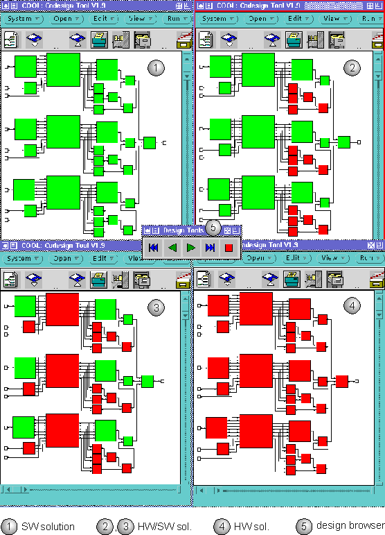
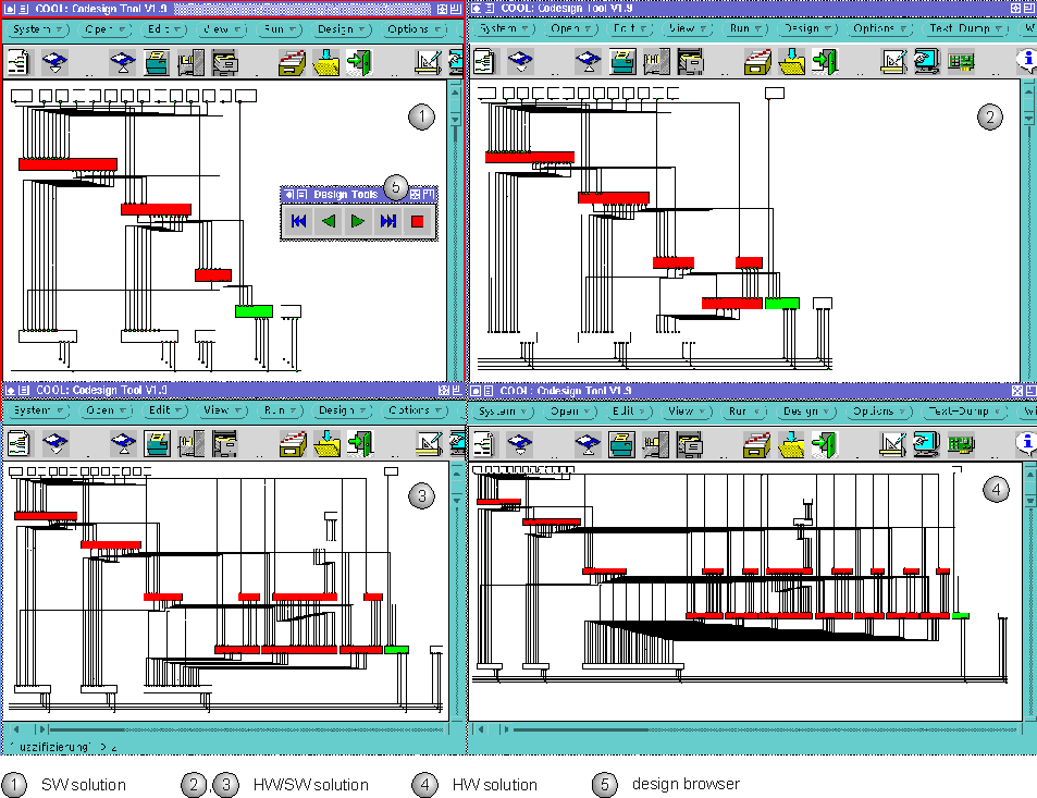
Therefore, the designer should be able to compare these different implementations of the system, as depicted in the figure depicted above. For this purpose, a design viewer (5) has been integrated in the graphical user environment of COOL with which the designer is able to explore the design space. For each solution the structural system specification is colored. The user can iteratively load all designs stored in the design library and can get detailed information for each design, such as the design costs, the resulting schedule and a lot of statistics. Thus, the designer is able to select the best design corresponding to his personal preferences. Four different partitions of the fuzzy system are depicted, ranging from a pure software solution (1) and mixed hardware/software implementations (2),(3) to a pure hardware (4).
After hardware/software partitioning, COOL generates a netlist of the complete hardware/software system during co-synthesis. In the following figure, the corresponding netlists for the partitions are depicted.
Finally, the generated netlist can be simulated with the help of the interface to Vantage Optium}. Thus, the designer is able to compare the results of simulating the implementation-independent system specification with the results of co-simulating the generated netlist. In the following figure, both the results of simulating the system specification and the generated netlist of the fuzzy system are depicted.
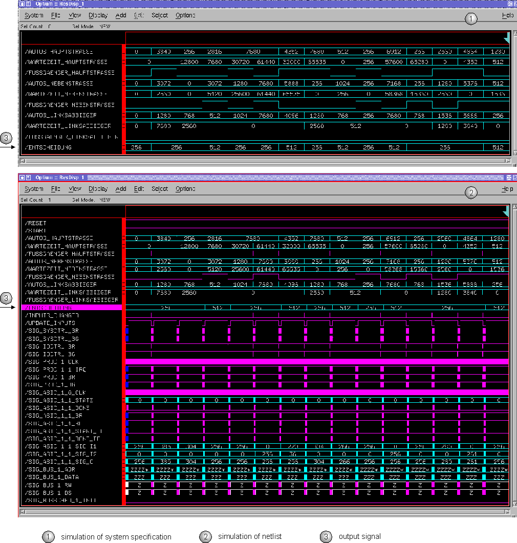
Clearly, the simulated waveforms for the output signal (3) are identical for simulating the system specification (1) and the refined hardware/software implementation (2). The main difference is that if an input signal changes its value, the output signal simultaneously changes without any delay when simulating the system specification. The reason for this is that the system specification does not contain any timing construct. In contrast, when simulating the netlist a delay occurs between the points of time where input and output values change. The reason for this is that the refined hardware/software specifications contain timing information, e.g. the hardware description works synchronously to the clock. However, the results for the output signals are the same.